Sri Yantra: Drawing Sacred Geometry in LaTeX
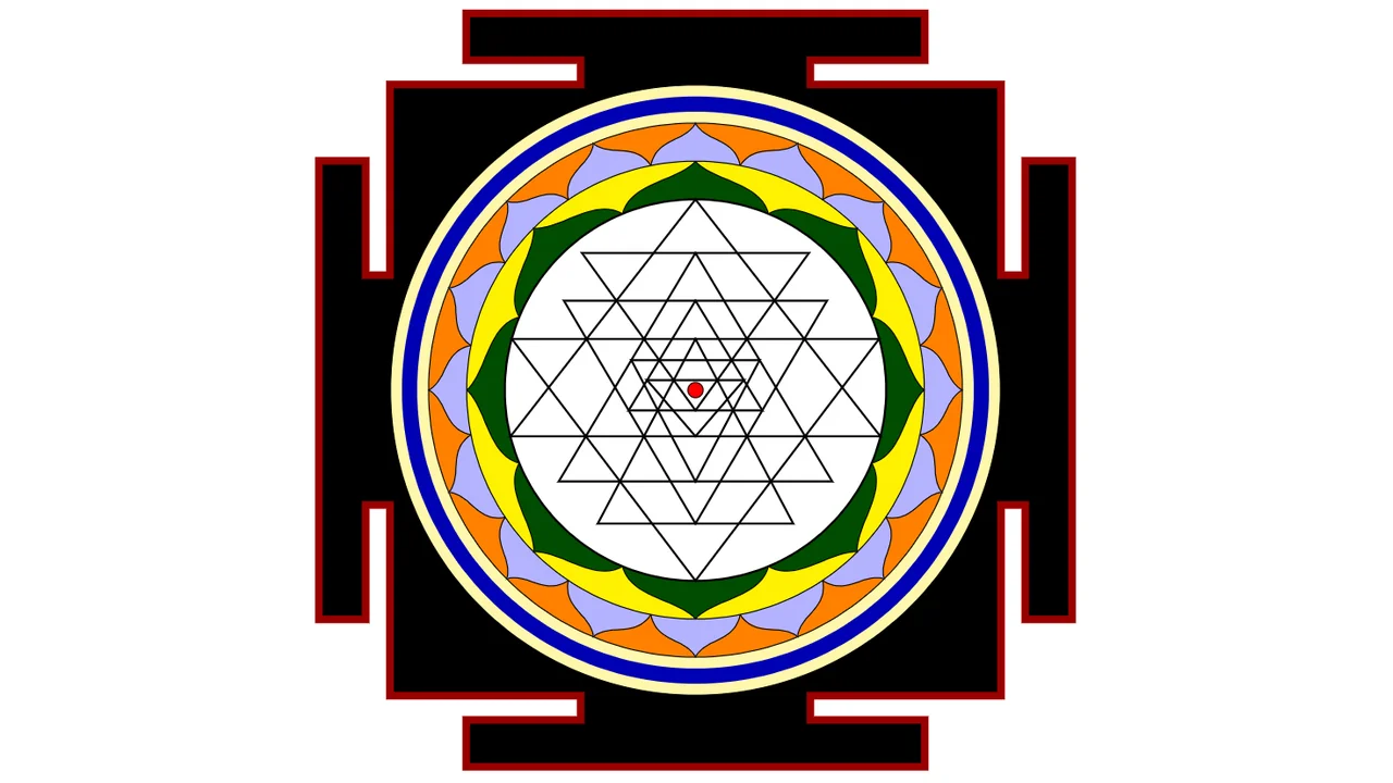
The Sri Yantra (also known as Sri Chakra) is one of the most mathematically complex geometric diagrams from ancient India, dating back to at least the 7th-8th century A.D. Its visual structure symbolizes the harmony of the cosmos and the unity of masculine (Shiva) and feminine (Shakti) energies.
Drawing the Sri Yantra manually is a challenging feat, as it requires highly precise coordinates to ensure all intersecting lines meet exactly at their cross points. In this article, we will explore how to construct a mathematically precise Sri Yantra diagram using TikZ in LaTeX.
Introduction
Geometrically, the Sri Yantra is formed by the intersection of nine principal triangles (4 pointing upward representing the masculine Shiva energy, and 5 pointing downward representing the feminine Shakti energy).
The intersection of these nine triangles creates a central matrix of 43 smaller triangles, surrounding a single central dot called the Bindu. The entire structure is encircled by lotus petal rings (8 petals in the inner ring and 16 petals in the outer ring), enclosed by a temple gateway frame called the Bhupura.
Due to its high complexity, even a tiny coordinate offset will create gaps or empty polygons at line intersection points. The code below uses verified coordinates refined through numerical optimization processes to ensure optimal precision.
Complete LaTeX Code
Here is the complete LaTeX code using the TikZ library (backgrounds and math) to draw the Sri Yantra:
\documentclass[tikz,border=2mm]{standalone}
\usetikzlibrary{backgrounds,math}

\begin{document}

\pgfdeclarelayer{minus1}
\pgfdeclarelayer{minus2}
\pgfdeclarelayer{minus3}
\pgfsetlayers{minus3,minus2,minus1,background,main}

\begin{tikzpicture}
% Base parameters
\def\cx{150}
\def\cy{150}
\def\scale{0.025}
\def\triangleData{%
{53.65669559977147}{123.20508075688774}{250}{246.34330440022853}{0}% D1
{52.984011026495736}{174.24660560764943}{50}{247.01598897350425}{1}% U1
{98.71823312733801}{220.03828947357886}{123.20508075688774}{201.281766872662}{1}% U3
{78.26467997914015}{197.92315674002487}{78.10499177949904}{221.73532002085986}{1}% U2
{90.4856922951427}{78.10499177949904}{160.66014976539617}{209.51430770485734}{0}% D3
{80.98384838952128}{103.12199145016105}{220.03828947357886}{219.0161516104787}{0}% D2
{114.9488500600036}{160.66014976539617}{103.12199145016105}{185.0511499399964}{1}% U4
{116.35142605010424}{134.30757626706648}{197.92315674002487}{183.64857394989576}{0}% D4
{124.61190803072795}{144.79777263138968}{174.24660560764943}{175.38809196927207}{0}% D5
}

% Function to transform and draw triangle
% Usage: \drawtriangle{x1}{y1}{x2}{y2}{x3}{y3}
\newcommand{\drawtriangle}[6]{%
\draw[thick] ({((#1-\cx)*\scale)},{(-(#2-\cy)*\scale)}) -- ({((#3-\cx)*\scale)},{(-(#4-\cy)*\scale)}) -- ({((#5-\cx)*\scale)},{(-(#6-\cy)*\scale)}) -- cycle;%
}

% Macro to draw a triangle from array data
% Arguments: left_x, top/base_y, center_y, right_x, type
\newcommand{\drawTriangleFromData}[5]{%
\ifnum#5=0
  % Downward triangle
  \drawtriangle{#1}{#2}{\cx}{#3}{#4}{#2}%
\else
  % Upward triangle
  \drawtriangle{#1}{#2}{\cx}{#3}{#4}{#2}%
\fi
}

% Recursive macro to process triangle data
% Stops when it encounters \relax as the first argument
\def\processTriangleData#1#2#3#4#5{%
\ifx\relax#1\relax
  % End of data reached
\else
  \drawTriangleFromData{#1}{#2}{#3}{#4}{#5}%
  \expandafter\processTriangleData
\fi
}

% Outer circle
\draw[thick, fill=white!30!white] (0,0) circle (2.5cm);

% Center bindu
\draw[fill=red] (0,0) circle (0.1cm);

% Draw all triangles from triangleData array
\expandafter\processTriangleData\triangleData\relax\relax\relax\relax\relax

% Step 11: Outer Lotus Petals (8 petals)
\begin{scope}[on background layer]
\draw [fill=yellow] circle (3cm);
\foreach \i [evaluate=\i as \start using 22.5+45*\i] in {0,...,7}
  \draw[fill=green!30!black] (\start:2.5) .. controls ({\start-5}:2.85) and ({\start-17.5}:2.75) .. ({\start-22.5}:3) .. controls ({\start-27.5}:2.75) and ({\start-40}:2.85) .. ({\start-45}:2.5) arc [start angle={\start-45}, delta angle=45, radius=2.5cm]--cycle;
\end{scope}

% Step 12: Outer Lotus Petals (16 petals)
\begin{pgfonlayer}{minus1}
\draw [fill=orange] circle (3.5cm);
\foreach \i [evaluate=\i as \start using 11.25+22.5*\i] in {0,...,15}
  \draw[fill=blue!30] (\start:3) .. controls ({\start-2.5}:3.35) and ({\start-8.75}:3.25) .. ({\start-11.25}:3.5) .. controls ({\start-13.75}:3.25) and ({\start-20}:3.35).. ({\start-22.5}:3) arc [start angle={\start-11.25}, delta angle=22.5, radius=3.5cm]--cycle;
\end{pgfonlayer}

% Step 13: Concentric Circles
\begin{pgfonlayer}{minus2}
\draw [fill=yellow!39] circle (4cm);
\draw [line width=2mm, blue!70!black] circle (3.75cm);
\end{pgfonlayer}

% Step 14: Bhupura (Square Temple Gates)
\begin{pgfonlayer}{minus3}
\node [fill=black, minimum size=8cm] (b) {};
\node [fill=black, minimum width=9.25cm, minimum height=3cm] (bh) {};
\node [fill=black, minimum height=9.25cm, minimum width=3cm] (bv) {};
\node [fill=black, minimum height=6mm, minimum width=6cm] at (bv.north) (bn) {};
\node [fill=black, minimum height=6mm, minimum width=6cm] at (bv.south) (bs) {};
\node [fill=black, minimum width=6mm, minimum height=6cm] at (bh.west) (bw) {};
\node [fill=black, minimum width=6mm, minimum height=6cm] at (bh.east) (be) {};
\draw [red!60!black,line width=1mm]%
(be.south west)-|(be.north east)-|(bh.north-|be.west)-|(b.north east)-|(bv.east|-bn.south)-|(bn.north east)-|(bn.south west)-|(b.north-|bv.west)-|(b.west|-bh.north)-|(bw.north east)-|(bw.south west)-|(bw.east|-bh.south)-|(b.south west)-|(bv.west|-bs.north)-|(bs.south west)-|(bs.north east)-|(bv.east|-b.south)-|(b.east|-bh.south)-|cycle;
\end{pgfonlayer}

\end{tikzpicture}
\end{document}
The output of the code is as follows:
Detailed Code Explanation
Let’s dissect the main components of the LaTeX code:
1. Drawing Layers (PGF Layers)
To render outer decorative details (such as the lotus petals and the Bhupura gates) behind the main intersecting triangles, we declare custom layers:
\pgfdeclarelayer{minus1}
\pgfdeclarelayer{minus2}
\pgfdeclarelayer{minus3}
\pgfsetlayers{minus3,minus2,minus1,background,main}
These layers are stacked from bottom (minus3) to top (main), ensuring that background patterns do not overlap or obscure the central vector lines of the triangles.
2. Coordinate System Mapping
The SVG coordinates of the triangles were originally mapped with a center at and a radius of 100. In TikZ, we want a coordinate space centered at with a radius of 2.5cm. We define the transformation:
- Scaling factor: (
\scale) - X-axis transformation:
- Y-axis transformation:
We package this into the
\drawtrianglemacro:
\newcommand{\drawtriangle}[6]{%
\draw[thick] ({((#1-\cx)*\scale)},{(-(#2-\cy)*\scale)}) -- ({((#3-\cx)*\scale)},{(-(#4-\cy)*\scale)}) -- ({((#5-\cx)*\scale)},{(-(#6-\cy)*\scale)}) -- cycle;%
}
3. Recursive Macro Parsing (\processTriangleData)
Instead of issuing individual \draw commands for nine different triangles, the vertices are structured into an array-like variable \triangleData with the structure:
{left_x}{top/base_y}{center_y}{right_x}{type}
The recursive macro \processTriangleData reads these parameters sequentially and automatically terminates when it encounters the \relax keyword. This makes the code highly modular and compact.
4. Bezier Curves for Lotus Petals
The lotus petals are drawn automatically using loops (\foreach) combined with Bezier control points:
\foreach \i [evaluate=\i as \start using 22.5+45*\i] in {0,...,7}
  \draw[fill=green!30!black] (\start:2.5) .. controls ({\start-5}:2.85) and ({\start-17.5}:2.75) .. ({\start-22.5}:3) ...
This algorithmically draws symmetric, curved petals at specified angular intervals around the concentric circles.
5. Bhupura Temple Gate
The Bhupura (outer border structure) is formed by stacking multiple rectangular nodes horizontally and vertically to build the signature four-sided gate contour, which is then outlined with a single, continuous path \draw tracing the outer boundary of the node coordinates.
How to Compile the Document
- Ensure you have a LaTeX editor/distribution (like TeX Live, MiKTeX, or Overleaf) ready.
- Save the code above into a file named
sri-yantra.tex. - Compile using the pdfLaTeX or XeLaTeX engine.
- The
standalonedocument class withborder=2mmwill crop the output PDF precisely to the drawing’s dimensions, leaving no empty space.
Conclusion
The Sri Yantra is a prime example of how ancient iconography embeds profound geometric complexity. With the help of TeX macro programming and TikZ vector capabilities in LaTeX, this sacred geometry can be generated with absolute mathematical accuracy, presenting an intriguing study in math, art, and graphics programming. Happy TeXing!